This study analyzes the causes of surface defects in high-frequency welded pipe billets, specifically, linear indentations and molten metal pits caused by the upper extrusion rollers. To address these issues, the design parameters of the upper extrusion rollers were optimized. By increasing the hole radius of the upper rollers, the “heel gap” was enlarged, effectively eliminating the linear indentations on the pipe surface. Additionally, reducing the width of the roller surface increased the roll gap, which successfully prevented the formation of molten metal pits near the weld seam.
In 2010, the a Steel Pipe Company established a 219 mm high-frequency welded pipe production line, incorporating an 8K2H high-frequency welding unit imported from ABBEY International (USA). Although the unit was originally designed to produce pipes with diameters ranging from 114.3 to 219.1 mm and wall thicknesses between 4.8 and 13.8 mm, in practice it exclusively manufactures 193.7 mm welded tube billets. These billets undergo hot tension reduction to produce tubes of various diameters, followed by full-body heat treatment and threading to become finished oil casings.
During the production of 193.7 mm billets with a wall thickness of 7.34 mm, linear indentations frequently appeared on the tube surface due to the outer edge of the upper extrusion roller in the five-roller welding frame. When producing billets with wall thicknesses exceeding 10 mm, additional defects—such as weld nodules being pressed into the upper rollers, causing surface pitting—were also observed. By analyzing the root causes of these defects and optimizing the roll gap, hole radius, and roller width, the surface quality of the welded pipe billets was significantly improved.
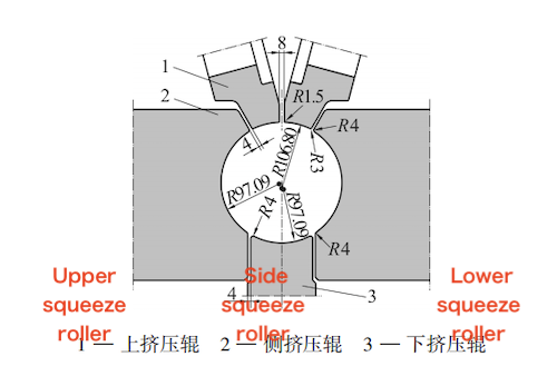
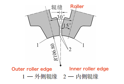
The welding extrusion rollers of the 219 mm high-frequency welded pipe unit adopt a five-roller configuration. The hole radius of the upper extrusion roller is 106.80 mm, while the hole radius of both the side and lower extrusion rollers is 97.09 mm. The inner edge arc chamfer radius of the upper extrusion roller is 1.5 mm, and the outer edge arc chamfer radius is 3 mm. For the side and lower extrusion rollers, the edge arc chamfer radius is 4 mm. The roller gap between the upper extrusion rollers is designed to be 8 mm; the gap between the upper and side extrusion rollers is 4 mm, as is the gap between the side and lower extrusion rollers. The basic dimensions of the welding extrusion rollers are shown in Figure 1, and the position of the upper extrusion roller is illustrated in Figure 2. Under ideal conditions, the hot-rolled steel strip forms a perfect circle after the forming and welding extrusion process.
As shown in Figure 1, the hole radius of the upper extrusion roller is 1.10 times that of the side extrusion roller. This design creates a slight gap between the outer surface of the upper extrusion roller and the ideal circular profile of the tube, referred to as the "heel gap." Due to the presence of this heel gap, the force exerted by the inner surface of the upper extrusion roller during the welding extrusion process is greater than the force on the outer surface. This imbalance is beneficial for welding extrusion, as it facilitates the expulsion of molten metal and helps reduce the indentation left by the outer edge of the upper extrusion roller on the welded pipe.

Figure 1 Basic dimensions of welding squeeze rollers

Figure 2 The position of the upper extrusion roller
During the installation, commissioning, and trial production of the high-frequency welded pipe unit, it was observed that when producing 193.7 mm welded pipe blanks with a wall thickness of 7.34 mm, particularly when the butt weld joint of the steel strip passes through the welding extrusion rollers, misalignment often occurs due to the unstable shape of the leading and trailing ends of the steel strip. The outer edge of the upper extrusion roller can easily create a linear indentation on the side of the pipe blank where the misalignment is more severe, and in extreme cases, a small step may form. Meanwhile, the weld bead (molten metal) tends to shift toward the side of the pipe blank with less misalignment. Due to its size and unevenness, the weld bead is prone to being pressed into and rolled over by the upper extrusion roller, resulting in pressure pits on the pipe surface.
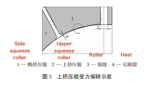
Under ideal conditions, a “heel gap” is formed between the outer edge of the upper extrusion roller and the welded tube. However, in actual production, due to the unbalanced forces at the roller edge, the torque generated by the upper extrusion roller causes it to rotate inward toward the weld side. When there is excessive bearing clearance or bearing wear, the heel gap is reduced or even eliminated. This also leads to a reduction in the roller gap between the upper extrusion rollers, increasing the likelihood of the outer roller edge of the upper extrusion roller causing surface indentations on the pipe blank. Simultaneously, the inner roller surface compresses the weld bead, forming pressure pits on both sides of the weld.

Figure 3 The force deflection of the upper extrusion roller
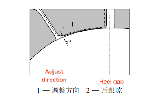
To reduce surface defects on the welded tube billet caused by the upper extrusion rollers, the two upper rollers were each adjusted outward by approximately 2 mm, increasing the roller gap between them and enlarging the “heel gap” between the upper extrusion rollers and the welded tube billet. After this adjustment, during the production of welded tube billets with a 7.34 mm wall thickness and a diameter of 193.7 mm, defects such as linear indentations and weld pits were significantly reduced, although not completely eliminated. The relationship between the roller gap and the heel gap of the upper extrusion rollers is illustrated in Figure 4.

Figure 4 The relationship between the roller gap and the heel gap of the upper extrusion roller
To effectively eliminate the indentations caused by the outer edge of the upper extrusion roller on the welded tube billet, the hole radius of the upper extrusion roller was increased from 1.10 times to 1.15 times the hole radius of the side extrusion roller. Specifically, the hole radius was adjusted from 106.80 mm to 111.65 mm, further increasing the heel gap between the upper extrusion roller and the welded tube billet. When this optimized upper extrusion roller was used to produce welded tube billets with a wall thickness of 7.34 mm and a diameter of 193.7 mm, the linear indentations previously caused by the outer edge of the upper extrusion roller were effectively eliminated.
After optimizing the hole radius of the upper extrusion roller, a wall thickness of 8.9 mm can be stably produced. For welded tube billets with diameters below 193.7 mm, defects are essentially eliminated. However, when producing welded tube billets with a wall thickness of 10 mm and a diameter of 193.7 mm, weld nodules may appear if the plate shape is poor. This issue becomes especially serious when producing high-collapse-resistance casings with a wall thickness of 12.5 mm.
To ensure stable production of thick-walled welded pipes, an analysis of the upper extrusion roller was conducted, revealing the following points:
- When producing thick-walled pipes, the extrusion force is high, resulting in more molten metal being expelled.
- The upper extrusion roller endures significant force and torque during thick-walled pipe production. Assembly gaps, such as those between the shaft and the roller hole, or caused by bearing wear, can cause the roller to deflect toward the weld seam (Figure 3). This deflection reduces the roller gap and increases the likelihood of the molten metal being crushed by the roller, forming pits.
To maintain product quality, the bearings of the upper extrusion roller must be replaced each time thick-walled pipes are produced. During replacement, the bearing accuracy must be ensured, and the inner and outer rings should be tightly fitted. This helps reduce roller deflection toward the weld side. Additionally, the two upper rollers should be adjusted outward as much as possible to widen the roller gap. Although these measures have brought some improvement, fully eliminating the gap remains challenging. Under high force, the upper roller still visibly deflects toward the weld seam, and the problem persists.
To fundamentally resolve this issue, further analysis indicated the need to optimize the design of the upper extrusion roller by increasing the roller gap, achieved by reducing the roller surface width. Based on prior production experience, reducing the surface width of the upper extrusion roller by 1.5 mm increases the roller gap by 3 mm, expanding it from the original 8 mm to 11 mm. The optimized upper extrusion roller is shown in Figure 5. If pit defects still occur during thick-walled pipe billet production, the roller position can be laterally adjusted to further increase the gap. Using this redesigned upper extrusion roller for producing thick-walled welded pipe billets has produced excellent results.
Figure 5 The upper extrusion roller after optimization
(1) Moderately increasing the hole radius of the upper extrusion roller in high-frequency welding increases the "heel gap" between the roller and the welded pipe billet, which helps effectively eliminate linear indentation defects caused by the upper roller on the billet surface.
(2) Reducing the surface width of the upper extrusion roller and increasing the gap between rollers can effectively eliminate weld nodule pits near the weld seam.


